2019 Chevrolet Express 2500 · 2.8L Duramax (LWN)
ECM/PCM, TCM, and the high-speed GMLAN “CAN high loop.” Every pin below was read directly from GM’s 2019 Express/Savana Electrical Body Builder Manual (model-year exact, free from GM) and cross-checked against the 2022 Colorado/Canyon manual, which shares the E98 ECM. Factory schematic pages are embedded below — click any page to zoom.
Quick checks
Start here if you’re chasing a no-comm / U-code problem.
Bus health, 30 seconds
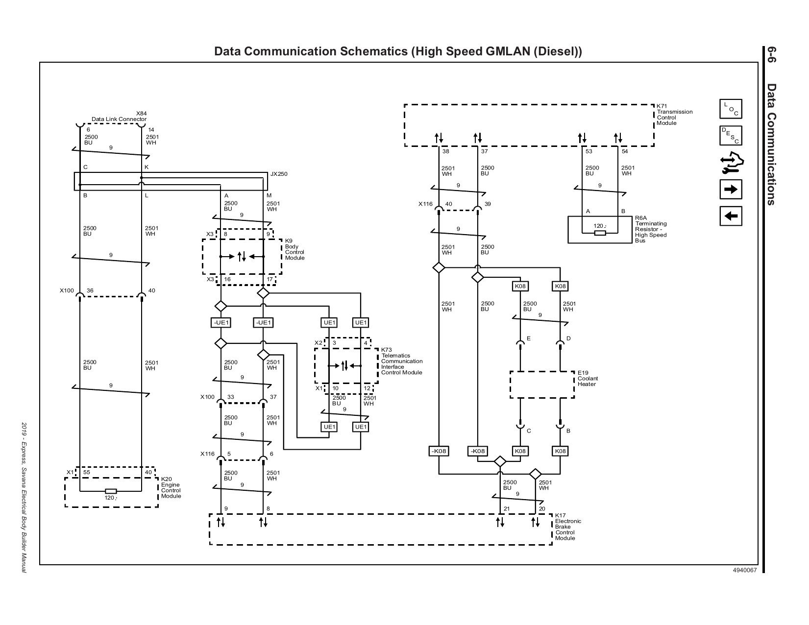
Key off, battery negative disconnected: measure across DLC pins 6 ↔ 14. Two 120 Ω terminators in parallel → ~60 Ω. Reading ~120 Ω means one end of the loop is lost; open or shorted means a broken or grounded pair.
The two terminators
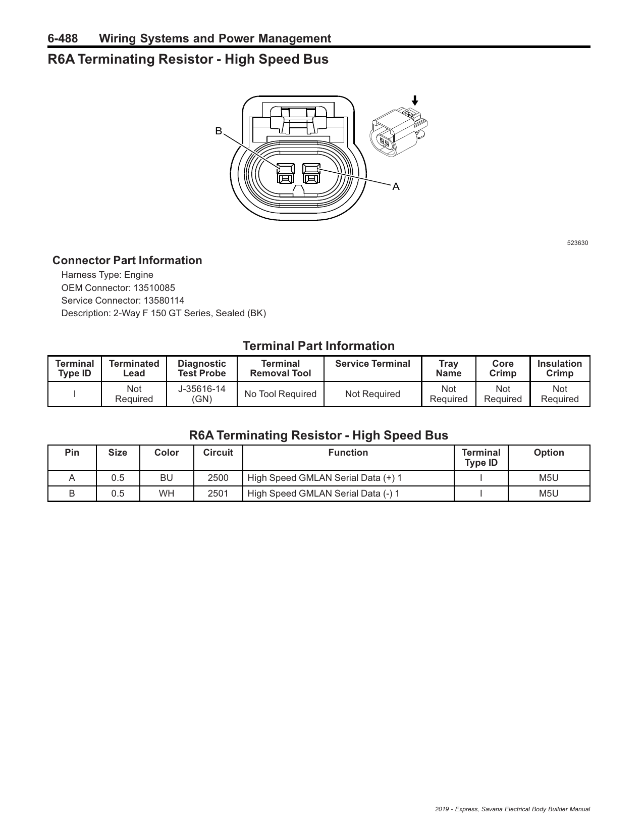
One 120 Ω resistor lives inside the ECM. The other is R6A, a separate 2-wire resistor plug in the engine compartment, wired after the TCM (pins 53/54). If you read ~120 Ω and the ECM talks, go find R6A and its pigtail first.
Best probe points
DLC pins 6/14 · JX250 splice pack behind the brake pedal at the carpet edge · X100 IP-to-engine harness connector, left-rear engine bay by the underhood fuse block · X116 engine-to-chassis connector (diesel only), engine compartment. Unplugging these splits the bus into halves for isolation.
Live case: bus collapses only when the TCM is plugged in
Symptoms: scan tool communicates only with the TCM unplugged; plug it in and both CAN lines sit ≈1.3 V instead of ≈2.6/2.4 V; blue (CAN High) reads near nothing; DLC normal with the TCM out.
| # | Where | Measure | Good | If bad → |
|---|---|---|---|---|
| 1 | DLC 6↔14, TCM unplugged, key off | Resistance | ≈120 Ω | ~120 Ω here is normal — R6A leaves with the TCM. If you see ~60 Ω with the TCM out, stop: something else is terminating and this page’s assumptions need a second look. |
| 2 | TCM harness connector, pins 53↔54 | Resistance | ≈120 Ω | Open = broken pigtail or R6A unplugged/missing. (This pair is dead-ended here with the TCM out — safe to measure.) |
| 3 | TCM harness connector, 53→gnd and 54→gnd | Resistance | open / MΩ | Low ohms = the chafed spot. The short run from the TCM connector to R6A in the engine bay is the prime suspect — it only joins the bus through the TCM, which is exactly your symptom. |
| 4 | Pin 66→B+ (check fuse F41UA “TCM BATT” 20 A) and pin 35 key on | Voltage under load (test light) | B+ | Dead feed = transceiver clamps the bus. Check the fuse before anything else. |
| 5 | Pin 65→battery negative | Resistance / voltage-drop cranking a load | <0.5 Ω | Bad ground = same clamping signature. Load-test it; a DMM alone will lie about a corroded ground. |
| 6 | On the TCM module pins: 37→65 and 38→65 | Resistance | high (kΩ+) | Near-zero = shorted transceiver, TCM is bad. Note: 37↔38 across the module should not read 120 Ω — this TCM has no internal terminator (R6A is external on this van). |
| 7 | The 66-way itself + R6A 2-way | Eyes | clean & tight | Green crust, backed-out or spread terminals, water in the sealed shell — all reproduce “bad TCM” symptoms. |
If steps 2–5 and 7 all pass, the module itself is condemned by elimination — step 6 just confirms it on the bench. If step 3 finds the short, follow the 53/54 pigtail from the connector to R6A before buying anything.
The CAN high loop (primary high-speed GMLAN)
Linear backbone, ECM at one end, R6A resistor at the other. CAN High is circuit 2500 (blue wire), CAN Low is circuit 2501 (white wire) everywhere on the diesel van. The DLC is a stub off the JX250 splice pack — it is not in the middle of the backbone.
left-rear engine bay
X116 5/6
engine bay
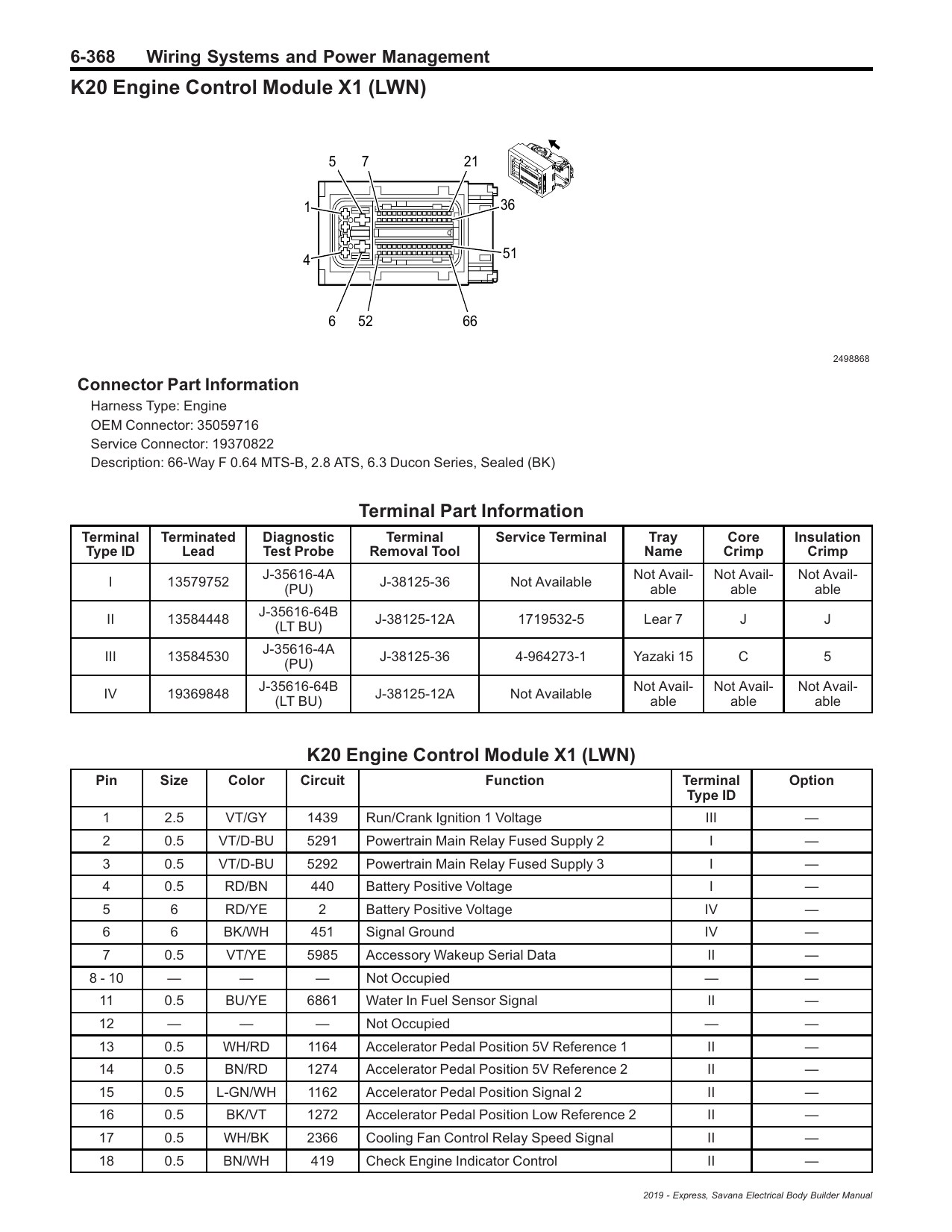
ECM (E98 / GM K20) — key pins
Three connectors, all female terminals, all on the engine harness: X1 66-way (OEM 35059716 / service 19370822), X2 96-way, X3 56-way. All CAN + power basics live on X1; glow plug drives on X2. Highlighted rows are the serial-data circuits.
| Pin | Wire | Ckt | Function |
|---|---|---|---|
| X1-1 | VT/GY | 1439 | Run/Crank Ignition 1 voltage |
| X1-2 | VT/D-BU | 5291 | Powertrain main relay fused supply 2 |
| X1-3 | VT/D-BU | 5292 | Powertrain main relay fused supply 3 |
| X1-4 | RD/BN | 440 | Battery positive voltage |
| X1-5 | RD/YE | 2 | Battery positive voltage (6 mm²) |
| X1-6 | BK/WH | 451 | Signal ground (6 mm²) |
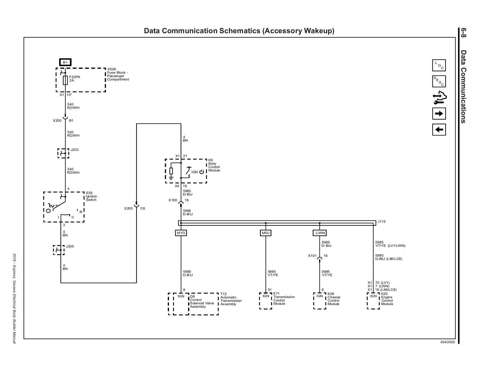
| X1-7 | VT/YE | 5985 | Accessory wakeup serial data |
| X1-11 | BU/YE | 6861 | Water-in-fuel sensor signal |
| X1-39 | WH | 7494 | HS GMLAN serial data (−) 3 — powertrain expansion bus |
| X1-40 | WH | 2501 | HS GMLAN serial data (−) 1 — CAN Low, primary bus |
| X1-50 | L-GN/GY | 465 | Fuel pump primary relay control (direct-wired — no CAN fuel module on LWN) |
| X1-51 | YE | 5991 | Powertrain relay coil control |
| X1-54 | D-BU/BK | 7493 | HS GMLAN serial data (+) 3 — powertrain expansion bus |
| X1-55 | BU | 2500 | HS GMLAN serial data (+) 1 — CAN High, primary bus |
| X2-13 | GY/BN | 1582 | Glow plug control 2 (direct drive, 2 mm²) |
| X2-14 | GY/YE | 1584 | Glow plug control 4 |
| X2-15 | GY/L-GN | 1583 | Glow plug control 3 |
| X2-16 | GY/D-BU | 1581 | Glow plug control 1 |
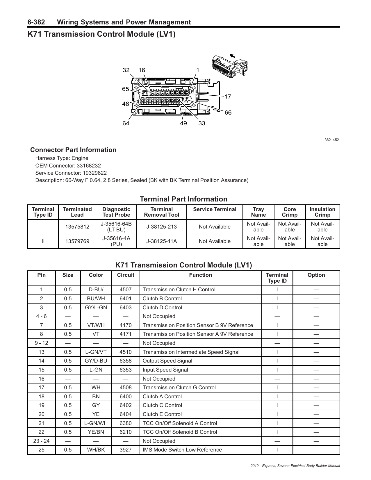
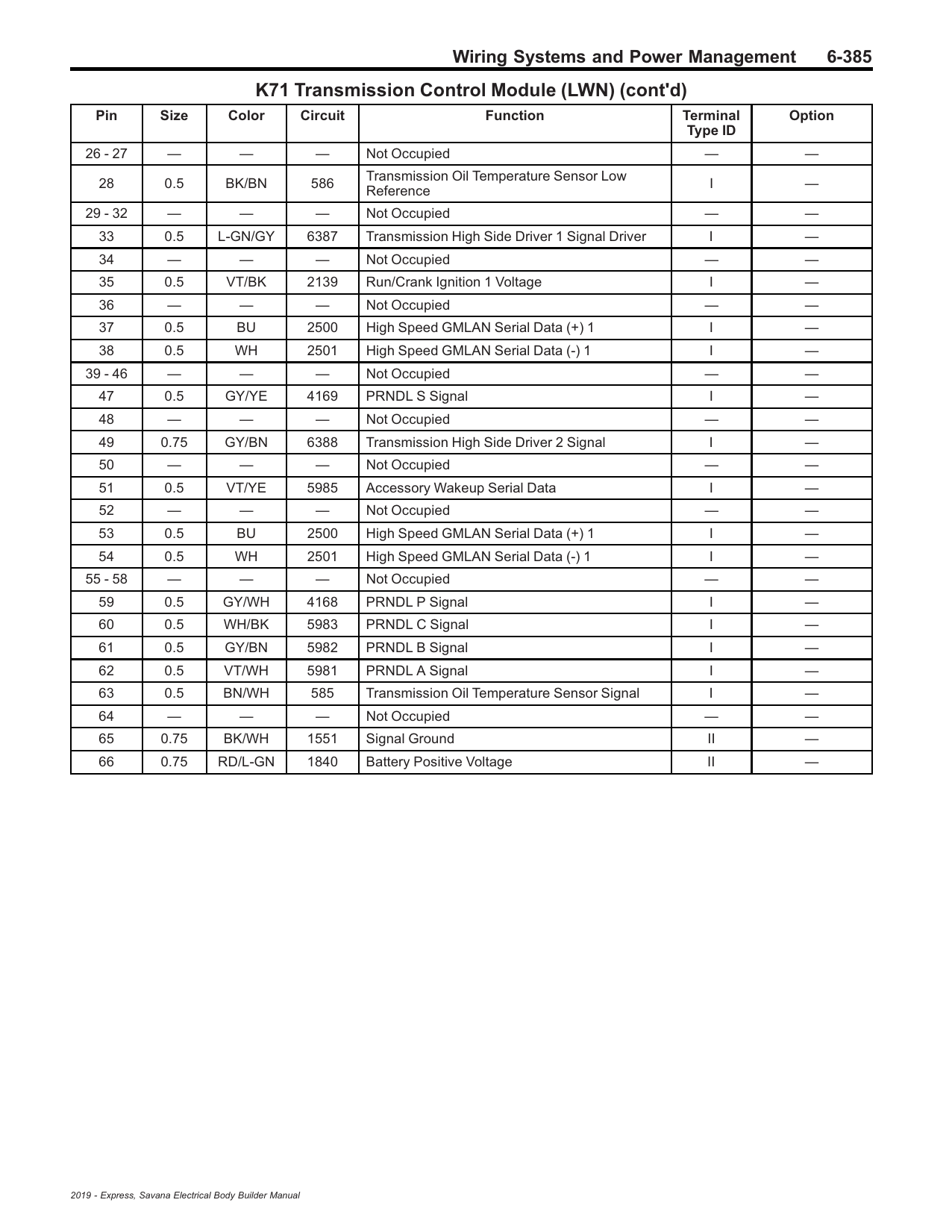
TCM (GM K71) — 8L90, key pins
The 2019 diesel van runs the 8L90 8-speed, RPO M5U (confirmed in the 2019 manual; the 6.0L gas kept the 6L90 “MYD”). The TCM is a standalone external module on the transmission assembly with one 66-way connector (OEM 33168232 / service 19329822). The aftermarket calls this hardware family “T87/T87A” — GM literature only ever says K71. Battery feed is underhood fuse F41UA “TCM BATT” 20 A.
| Pin | Wire | Ckt | Function |
|---|---|---|---|
| 28 | BK/BN | 586 | Trans oil temperature sensor low reference |
| 33 | L-GN/GY | 6387 | Transmission high-side driver 1 |
| 35 | VT/BK | 2139 | Run/Crank Ignition 1 voltage |
| 37 | BU | 2500 | HS GMLAN serial data (+) 1 — CAN High in |
| 38 | WH | 2501 | HS GMLAN serial data (−) 1 — CAN Low in |
| 47 | GY/YE | 4169 | PRNDL S signal |
| 49 | GY/BN | 6388 | Transmission high-side driver 2 |
| 51 | VT/YE | 5985 | Accessory wakeup serial data |
| 53 | BU | 2500 | HS GMLAN (+) 1 — CAN High out to R6A terminator |
| 54 | WH | 2501 | HS GMLAN (−) 1 — CAN Low out to R6A terminator |
| 59 | GY/WH | 4168 | PRNDL P signal |
| 60 | WH/BK | 5983 | PRNDL C signal |
| 61 | GY/BN | 5982 | PRNDL B signal |
| 62 | VT/WH | 5981 | PRNDL A signal |
| 63 | BN/WH | 585 | Trans oil temperature sensor signal |
| 65 | BK/WH | 1551 | Signal ground |
| 66 | RD/L-GN | 1840 | Battery positive voltage (fuse F41UA “TCM BATT” 20 A, underhood block) |
Two CAN pairs, one bus: 37/38 bring the backbone in; 53/54 send it out to the R6A terminator. Unplug the TCM and the R6A terminator drops off with it — a ~120 Ω DLC reading with the TCM unplugged is normal, not a second fault.
Factory pages: K71 connector face + full (LWN) pin table
Junctions, splices & the DLC
DLC (X84) — OBD-II port
| Pin | Wire | Ckt | Function |
|---|---|---|---|
| 1 | — | — | Low-speed GMLAN serial data (single wire) |
| 4 | — | — | Scan tool power ground |
| 5 | — | — | Common signal ground |
| 6 | BU | 2500 | HS GMLAN serial data (+) — CAN High |
| 14 | WH | 2501 | HS GMLAN serial data (−) — CAN Low |
| 16 | — | — | Battery positive (scan tool power) |
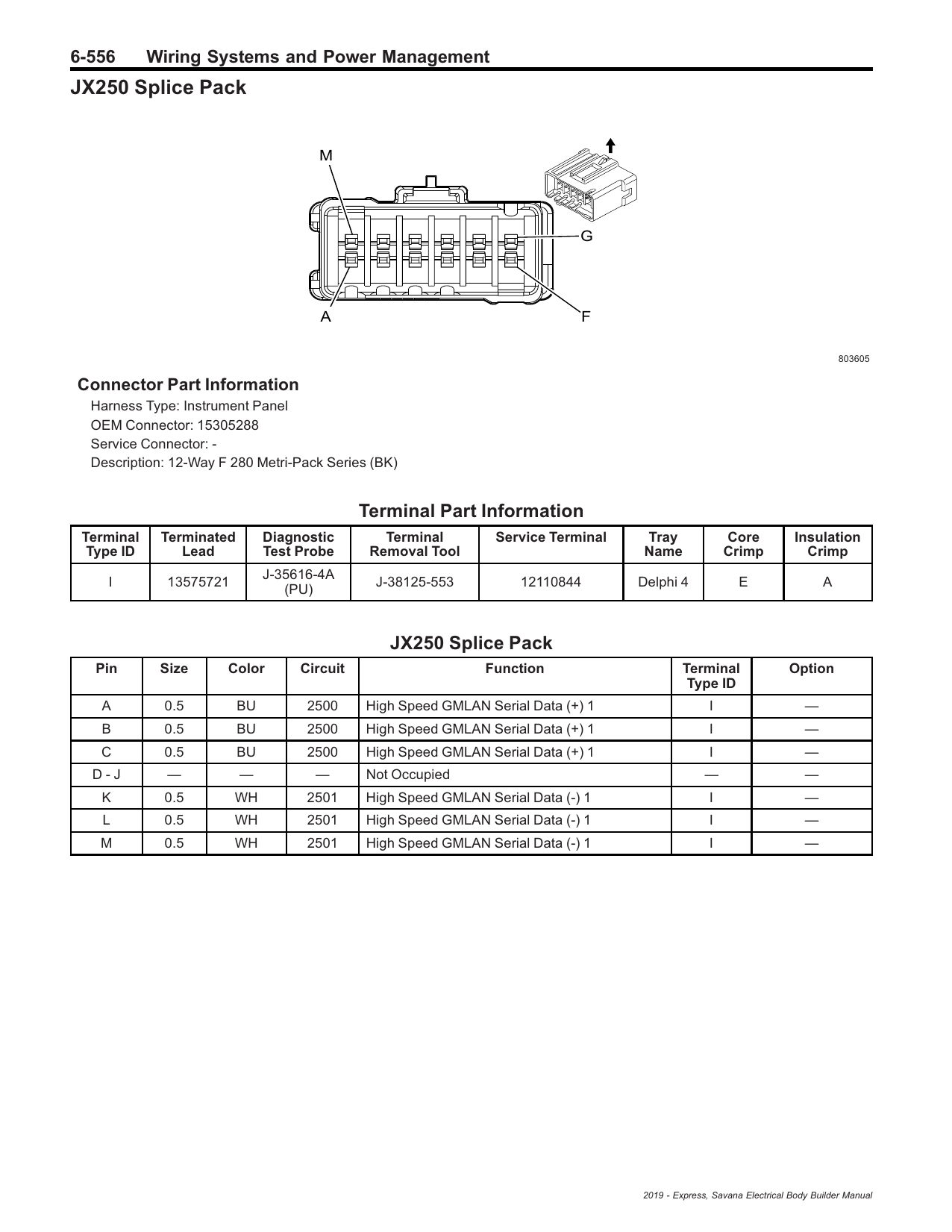
JX250 splice pack — where the bus branches
12-way Metri-Pack 280 (OEM 15305288), instrument panel harness, left front floor where the carpet ends behind the brake pedal, next to splice pack JX200. Pins A·B·C are all ckt 2500 (CAN High), K·L·M all ckt 2501 (CAN Low): one leg to the DLC, one leg toward the ECM via X100, one leg into the body/BCM side. Pull this pack and you can isolate all three directions from the driver’s seat.
Factory page: JX250 splice pack connector + pin table
R6A terminating resistor
Discrete 120 Ω resistor plug, engine compartment, 2-way F 150 GT-series sealed connector (OEM 13510085 / service 13580114), pin A = ckt 2500, pin B = ckt 2501. This is the terminator you can actually get your hands on — check it before condemning a module.
Factory page: R6A connector detail
In-line harness connectors on the CAN pair
| Conn | Joins | Location | CAN pins |
|---|---|---|---|
| X100 | IP harness ↔ engine harness | Left rear of engine compartment, near underhood fuse block and horn | 36/40 (ECM leg) · 33/37 (EBCM leg) |
| X116 | Engine harness ↔ chassis harness (LWN only) | Engine compartment | 5/6 · 39/40 (+ 32/33 expansion bus) |
| JX250 | 3-way splice: DLC / ECM leg / body leg | Behind brake pedal at carpet edge | A–C = 2500 · K–M = 2501 |
The other three buses (don’t mix them up)
| Bus | Circuits | Who’s on it | Terminators |
|---|---|---|---|
| Primary HS GMLAN | 2500 / 2501 | ECM, TCM, BCM, EBCM, DLC, (+OnStar K73, coolant heater E19) | ECM internal + R6A |
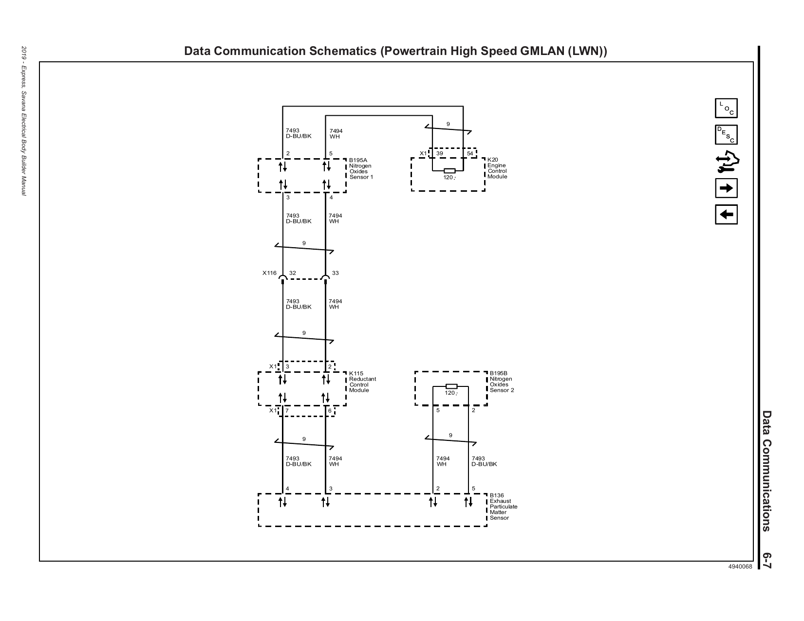
| Powertrain expansion (diesel only) | 7493 / 7494 | ECM (gateway, X1-54/39), NOx sensor 1, reductant/DEF module K115, NOx sensor 2, PM sensor B136 | ECM internal + NOx sensor 2 |
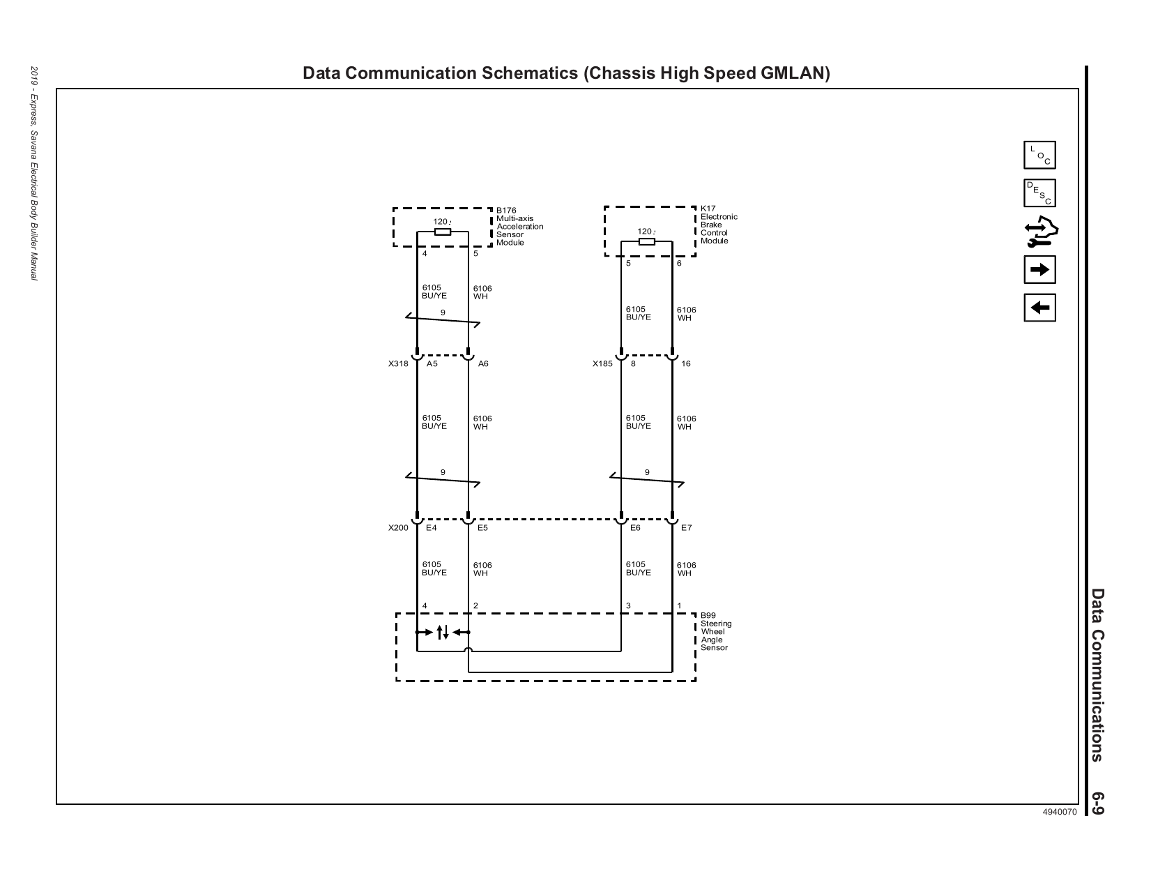
| Chassis HS GMLAN | 6105 / 6106 | Chassis expansion modules (K38 chassis control, trailering) — see schematic | see schematic |
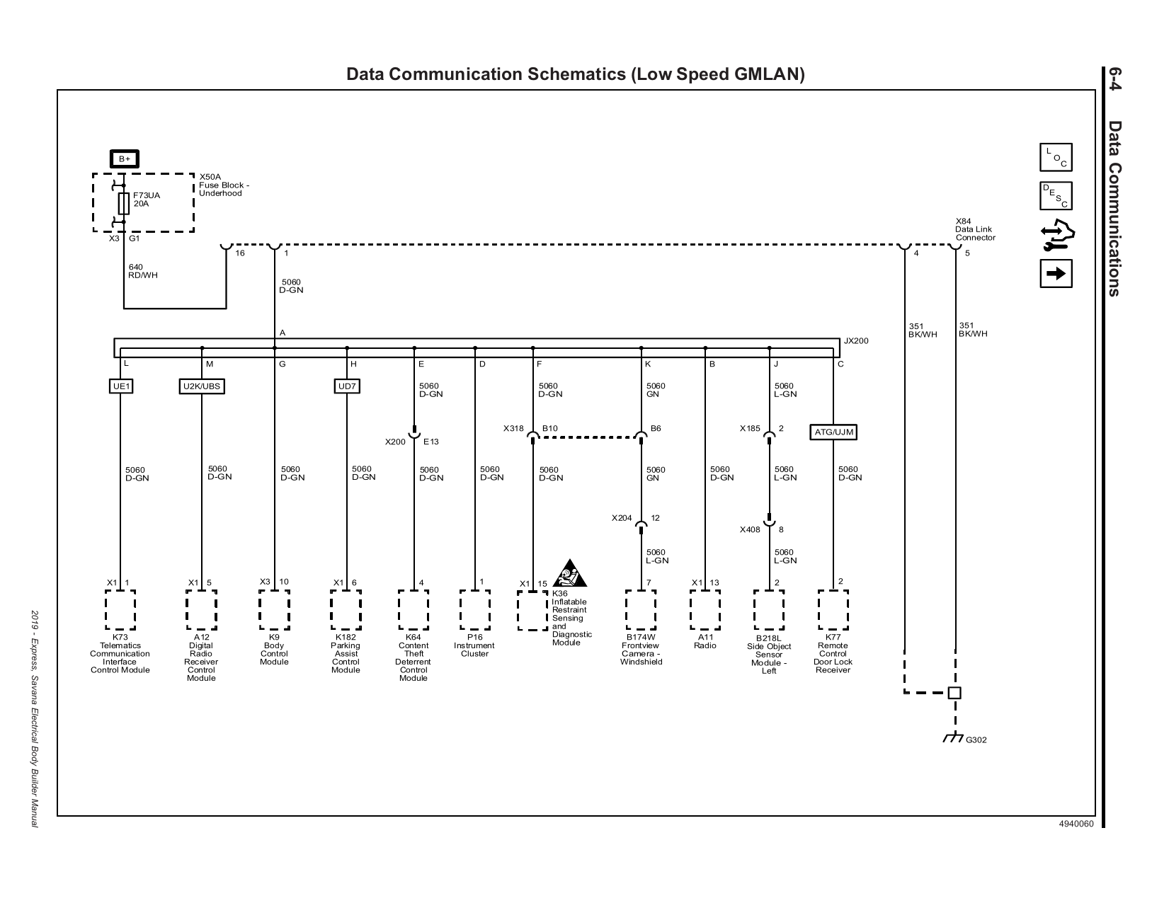
| Low-speed GMLAN | single wire, DLC pin 1 | IPC cluster, airbag SDM, radio, theft, chime, door locks — gatewayed by BCM | n/a (single wire) |
Factory schematic: Powertrain expansion bus (LWN) — NOx / DEF / PM sensors
Factory schematic: Chassis High Speed GMLAN
Factory schematic: Low Speed GMLAN (cluster, SDM, radio…)
Factory schematic: Accessory wakeup line (ckt 5985 — ECM/TCM wake signal)
Getting the complete factory diagrams
Free — official GM PDFs (source of everything on this page)
- 2019 Express/Savana Electrical Body Builder Manual (~35 MB, 823 pages) — data-comm schematics, module pin tables, connector faces, component locations, fuse maps. Model-year exact.
- 2019 Express/Savana chassis section — body/chassis supplement.
- 2022 Colorado/Canyon Electrical BBM — same E98 ECM; deeper LWN engine-harness detail (all 218 ECM pins).
- gmupfitter.com 2019 index — airbag supplement, spec sheets.
Paid — when you need every circuit in the van
| Source | Price | Notes |
|---|---|---|
| ACDelco TDS (GM SI) | ~$20–30 / 3 days | The actual dealer service info — complete VIN-exact schematics. Pricing changed July 2026; confirm at checkout. |
| ALLDATAdiy | $19.99 / mo · $59.99 / yr | Interactive color diagrams, single vehicle. Easiest UI; pricing verified live. |
| Mitchell1 DIY | $19.99 / mo · $39.99 / yr | Equivalent alternative; confirm Express is in their vehicle selector before paying. |
Dead ends (so you don’t waste time)
- charm.li (Operation CHARM) stops around MY2013 — no 2019 Express.
- BBB Industries free diagrams: discontinued.
- duramaxforum / dieselplace / coloradofans now sit behind a bot-wall for automated access; threads like “Anyone need wiring diagrams for free?” are still worth browsing by hand.
Verification log
How each claim was confirmed, and what’s still soft.
| Claim | Status | Evidence |
|---|---|---|
| ECM CAN High/Low = X1-55 / X1-40 | Confirmed ×2 | 2019 Express BBM pin table + schematic; identical in 2022 Colorado BBM (shared E98). |
| TCM CAN High/Low = 37 / 38 (out: 53 / 54) | Confirmed ×2 | 2019 Express BBM K71 (LWN) pin table + diesel schematic. Matches the previously unverified forum claim. |
| Terminators = ECM internal + discrete R6A | Confirmed | 120 Ω symbols on the 2019 diesel schematic at K20 and R6A; R6A located “in the engine compartment.” (Corrects the common assumption that the second resistor is inside a module.) |
| 2019 diesel trans = 8L90, RPO M5U | Confirmed | 2019 BBM RPO usage throughout (“K71 (M5U)”, fuse table, wakeup schematic branch tagged LV1/LWN). The “MQD” diesel RPO only appears in 2022+ documents. |
| No glow-plug or fuel-pump module on the CAN bus | Confirmed | Glow plugs driven directly from ECM X2-13…16; fuel pump via relay from X1-50. The K34 glow module some sources mention belongs to the old 6.6L LGH V8 vans, not the LWN. |
| “T87A” naming | Unsettled | GM literature only says K71. Aftermarket disagrees on whether the 8L90 unit is “T87” or “T87A” — irrelevant for wiring (pinout above is factory), matters only when ordering/flashing a replacement. |
| Body Builder Manual vs full SI | Scope note | The free BBM covers data-comm schematics, module pin tables and locations — everything on this page. For every last body/interior circuit diagram, use TDS or ALLDATA above. |